In this lesson we will be discussing microphones: one of the most basic and yet most necessary components of a sound system. Understanding a bit about microphone technology and their proper usage is key to obtaining the desired result. Using the right mic for the right job will determine the quality of your end product, whether live sound or a recording project. The adage, “garbage in, garbage out” can definitely apply to microphone choice. If the first step in your signal chain is less than optimal, you will never regain the loss. Even with all of the fancy audio tools at our disposal, there is no substitution for the right mic coupled with proper placement. Does this mean expensive? In a word, NO! The best mic for the job does not have to mean the most expensive. Actually in most cases, two important parts of the equation for choosing the best microphone for the job is budget and mic type. So, let’s try to gain an understanding of different types of microphones and some of the best uses for each microphone type. Then, with this knowledge, we will be better equipped to choose the right type of microphone for the application, and within a budget. Here is a handout listing a few of our staff’s favorite microphones for particular uses. You will also notice the type of each mic (Dynamic, Condenser, Ribbon).
In addition to what you will learn for your own benefit, you will also be equipped to help your worship team members properly use microphones. We will be covering a lot of info today, so please take notes!
The three primary types of professional microphones include the dynamic, condenser and ribbon.
First we have a SHURE SM58, the world standard ”live” vocal dynamic microphone for the last few decades.

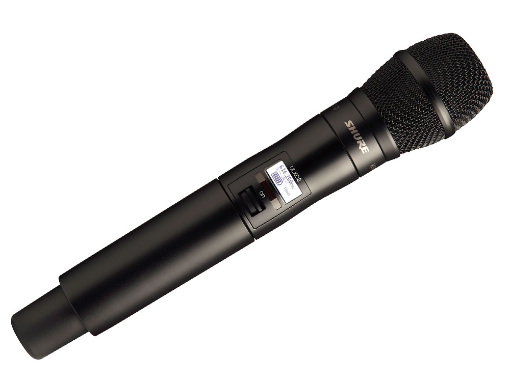
Next we have a wireless version of a SHURE KSM9, which is Shure’s premier vocal condenser microphone.
The third image Beyerdynamic M160, which is a end-address ribbon microphone which is commonly used for live performance and can be used for both vocal and instrument applications.

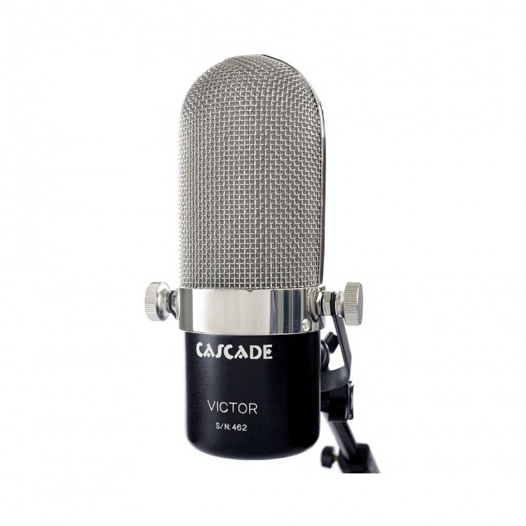
Finally, the Cascade VICTOR microphone is a large bi-directional side-address ribbon microphone. The Cascade microphone is primarily used in studio applications and is widely recognized for capturing electric guitar amps.
Dynamic mics create sound with a voice coil attached to the back of a diaphragm.
Condenser mics create sound with a metalized diaphragm which is one plate of a capacitor (an electronic circuit).
Dynamic mics are generally considered to have a “rugged” or “gutsy” sound
Condenser mics tend to produce a more natural sound and reproduce transients better.
¶ Microphone Construction
Below you see a cross sections of a dynamic, condenser and a ribbon mic as illustrated in section 10 of the Yamaha Sound Reinforcement Handbook
¶ Dynamic Mic
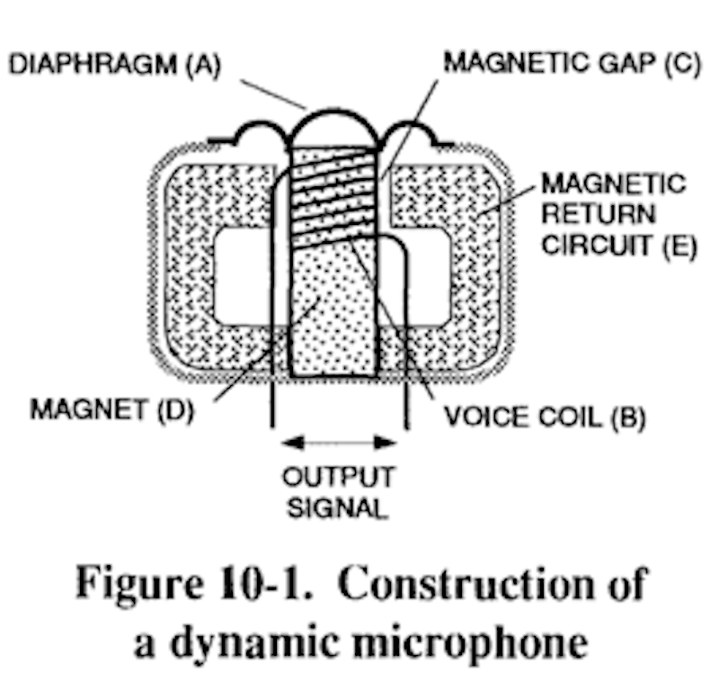
In a dynamic mic a flexibly-mounted diaphragm is coupled to a coil of fine wire. The coil is mounted in the air gap of a magnet such that it is free to move back and forth within the gap. When sound strikes the diaphragm, the diaphragm surface vibrates in response. The motion of the diaphragm couples directly to the coil, which moves back and forth in the field of the magnet. As the coil cuts through the lines of magnetic force in the gap, a small electrical current is induced in the wire. The magnitude and direction of that current is directly related to the motion of the coil, and the current thus is an electrical representation of the incident sound wave.
¶ Condenser Mic

The condenser mic has a gold-coated plastic diaphragm is mounted above a conductive back plate, which is often made of gold-plated ceramic. The diaphragm and back plate, separated by a small volume of air, form an electrical component called a capacitor (or condenser). A polarising voltage of between 9 and 48 volts is applied to the diaphragm by an external power supply, charging it with a fixed, static voltage. When the diaphragm vibrates in response to a sound, it moves closer to and father from the back plate. As it does so, the electrical charge that it induces in the back plate changes proportionally. The fluctuating voltage on the back plate is therefore an electrical representation of the diaphragm motion. Condenser microphone elements produce a signal voltage with almost no power. Thus they present a very high impedance. For these reasons, all condenser microphones incorporate an amplifier (pre-amp), which drives the microphone line. Its function is both to boost the signal level and to isolate the element from the lower impedance of the input to which the microphone is connected.
¶ Ribbon Mic
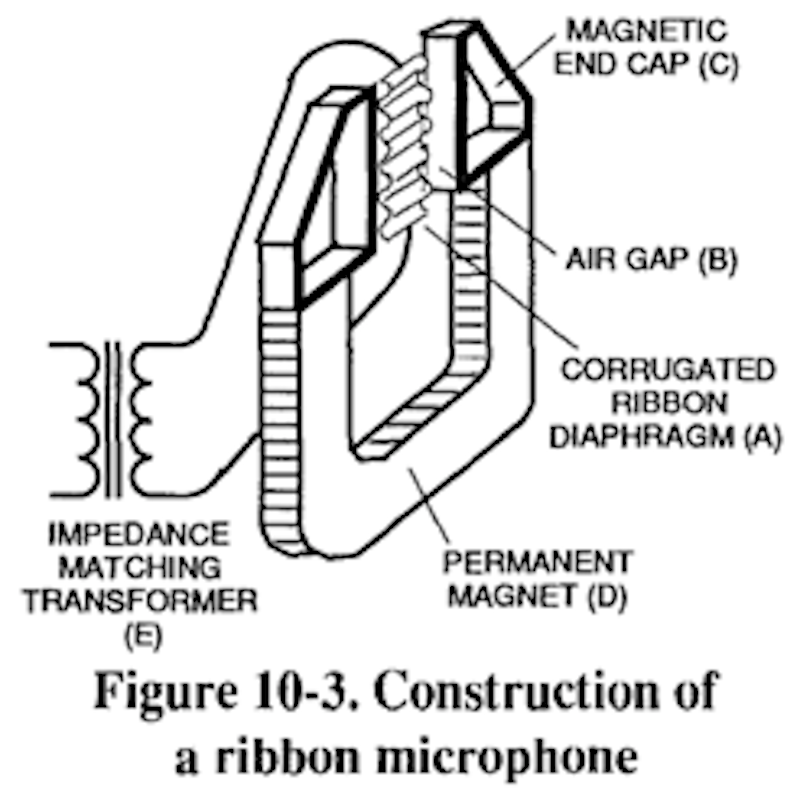
Ribbon microphones employ a transduction method that is similar to that of dynamics. A very light, thin, corrugated metal ribbon is stretched within the air gap of a powerful magnet. The ribbon is clamped at the ends, but is free to move throughout its length. When sound strikes the ribbon, ribbon, vibrates in response. As is the case with the dynamic coil element, the moving ribbon cuts the magnetic lines of force in the air gap, and a voltage is thereby induced in the ribbon. The voltage is very small and the ribbon impedance very low, so all ribbon microphones incorporate a built-in transformer. The transformer serves the dual functions of boosting the signal voltage and isolating the ribbon impedance from the load presented by the input to which the microphone is connected.
¶ Condenser Microphones
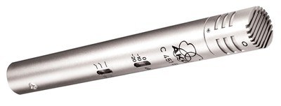
There are three classes of condenser microphones. The first is a classic AKG C 451 B which is considered a pencil style microphone defined by its straight, inline design.
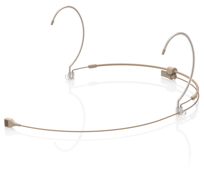
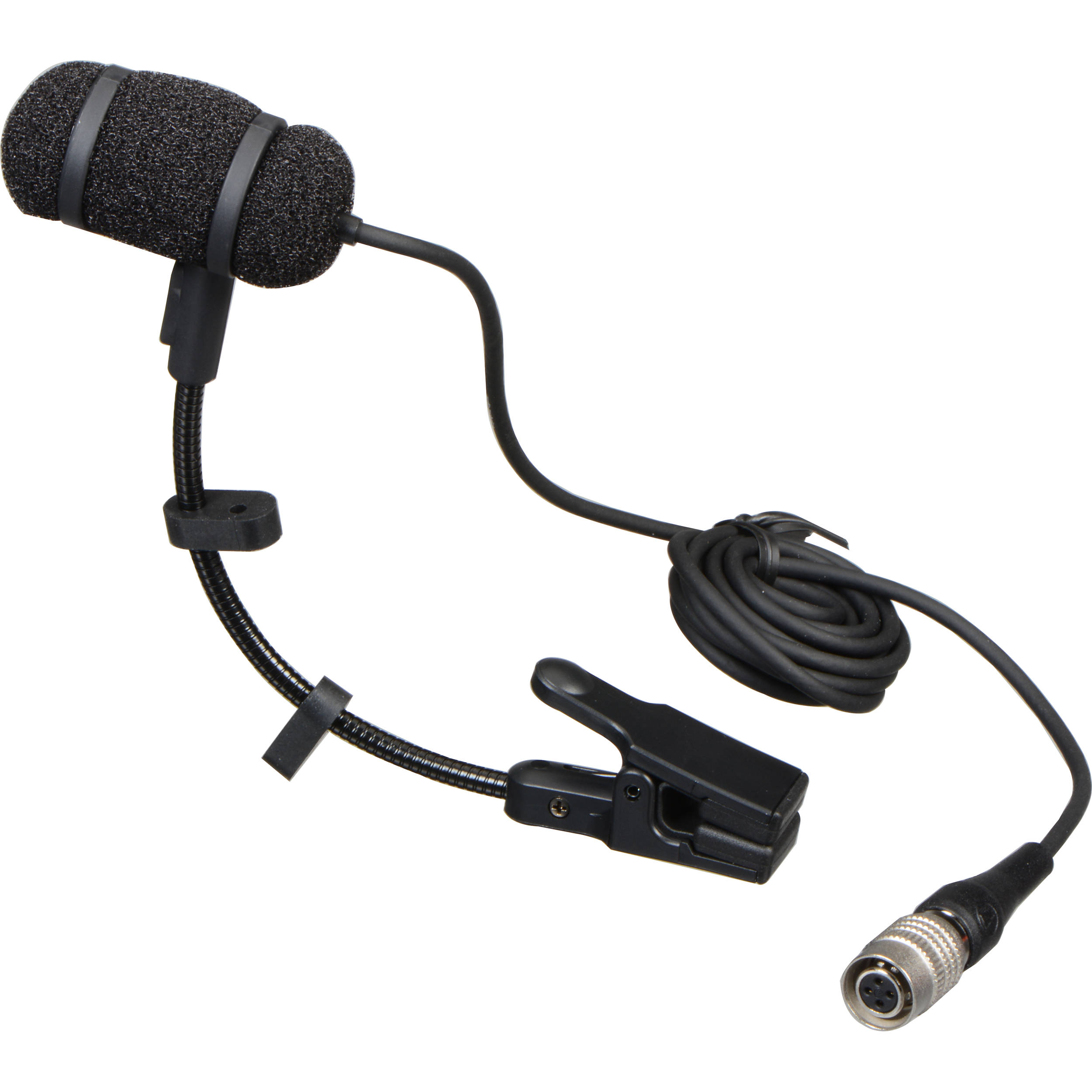
The two microphones below fall under the category of small diaphragm condenser microphones. The top is a miniature headset microphone and the bottom microphone is a specialty acoustic instrument microphone.
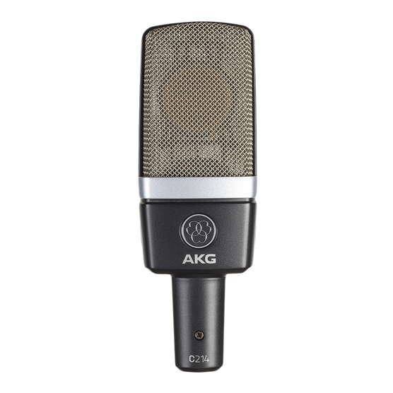
Finally, the AKG C214 is a single large diaphragm side-address studio condenser microphone which can be used for multiple instrument and vocal applications.
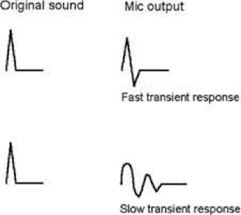
In dynamic microphone design, the main limitation on transient response is diaphragm mass, so condenser microphones generally exhibit better transient response than dynamics, and do the best job of capturing sounds with complex waveforms.
¶ Transient Wave
A transient wave is a sudden increase of a sound wave that decays rapidly after a short period of time.
This image represents a waveform with a fast, or sharp, transient peak. From the second illustration you may get a better sense of how our three types of microphones respond to the same transient signal.

¶ Signal Phase
Signal Phase is very critical throughout our signal chain. A signal cancellation can occur electrically when two identical audio signals of equal amplitude and of opposite polarity are combined. The physics of phase can have negative results. However, it can also be used to one’s advantage, in certain situations.
One such example of "shifting" phase to our advantage is inverting the phase between top and bottom snare microphones. In that most modern consoles have a simple 180 degree phase inversion switch, this is easily accomplished and makes comparing the results simple. One simple way to determine the best “phase” option is to flip phase on one mics of a multi-mic’ed instrument. One option will likely sound “fuller” or have a bigger low-end response. This is usually the best choice.
¶ Polarity Matters
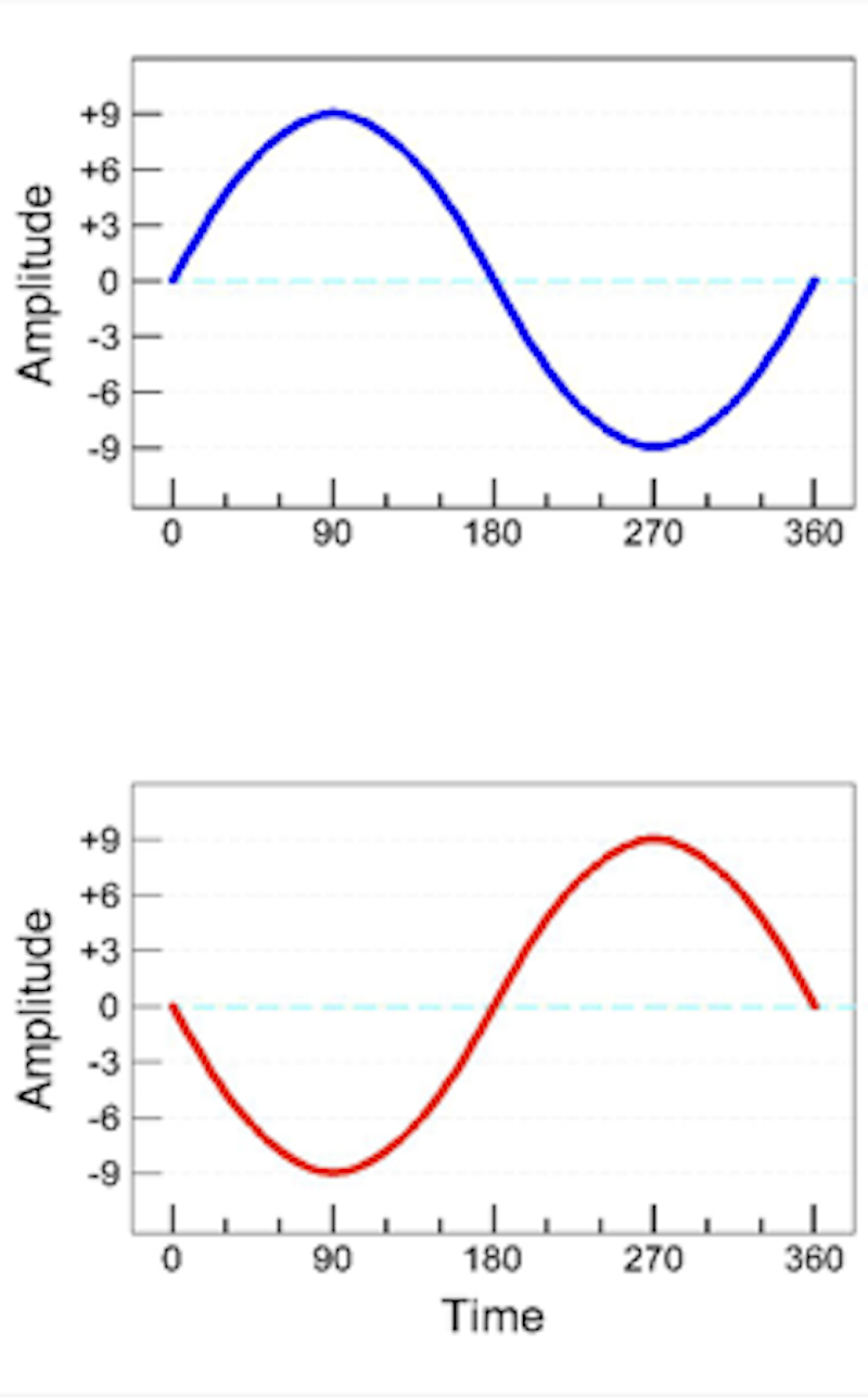
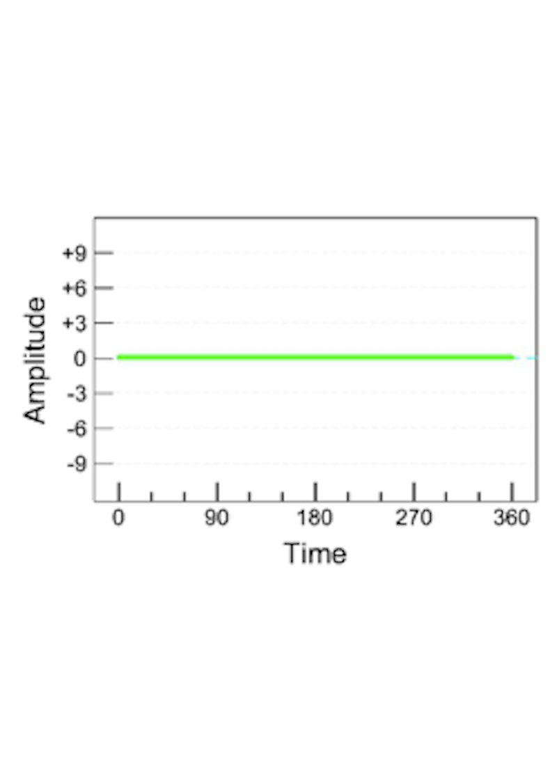
As we see in the illustration above, we have two sine waves of equal frequency and equal amplitude. The two waves are 180 degrees out of phase. As the two waves combine we see a simple math principle at work. At any time along the waveform the amplitude of the wave is equal but opposite. (+1 -1=0)
Inversely, if the two waves combine perfectly in phase, the frequency remains the same however, the amplitude is increased (doubled). This will result in the combined waves being twice as loud. (+1+1=2)
With this concept in mind, try walking across an auditorium during sound check. You may notice certain frequencies seem to get louder in certain spots while others seem to dip in volume or even disappear. This is the result of phase combining and/or cancellations of certain frequencies at certain spots in the room.
¶ Polar Patterns

The five classic polar patterns are:
- Omnidirectional — An omnidirectional pattern should pickup 360 degrees around the diaphragm with a relatively even frequency response.
- Cardioid — A basic cardioid pattern picks up directionally in front of the diaphragm and rejects signals entering from the back of the diaphragm.
- Supercardioid — A supercardioid pattern behaves similar to a cardioid pattern with the exception that there is more rejection at 90 degrees off-axis (side of the microphone). This pattern will also have a little bump at the rear of the diaphragm.
- Hypercardioid — A hypercardioid pattern is basically an enhanced supercardioid pattern. The microphone exhibits even more side-rejection, but the offset is a larger bump at the rear of the diaphragm.
- Bi-directional (“Figure 8”) — A bi-directional pattern, by its nature, is also a side-address microphone. This means that the diaphragm is suspended and faces the side of the microphone. Unlike a cardioid pattern, this design utilizes two back-to-back diaphragms and therefore its pick-up pattern is relatively similar from either side of the microphone. When viewing the polar pattern from above, the pattern will look like the numeral 8. With this image in mind, you will realize that this pattern has an area of rejection 90 degrees off-axis on either side.
Microphone polar patterns are one example of when "phasing" can work to our advantage. Phase differences between the front and rear of a microphone's diaphragm actually create the differing patterns. This is where the physics of phase cancellation is incorporated in the design of the microphone to produce a desired outcome.
¶ Cardioid
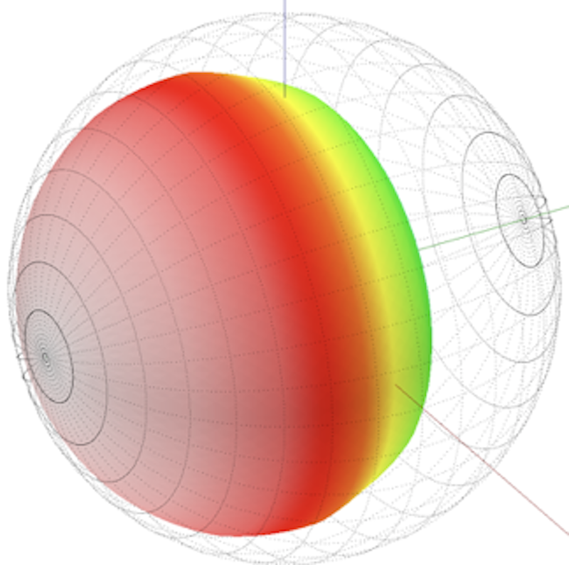
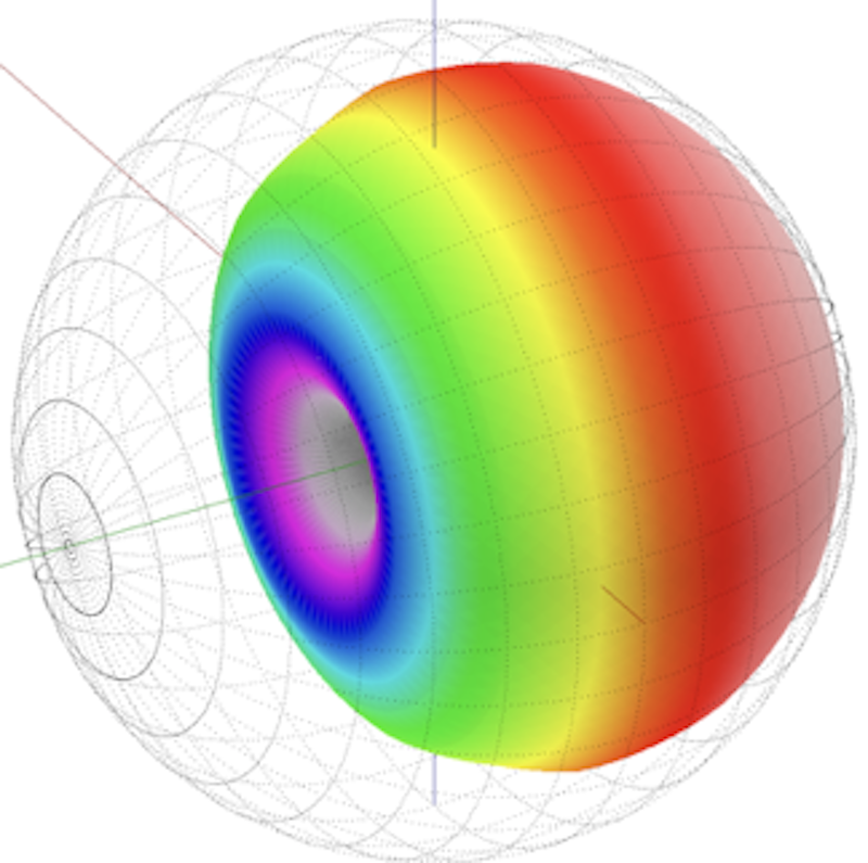
EASE 3D Audio Analysis Program of a Cardioid pattern.
¶ Supercardioid
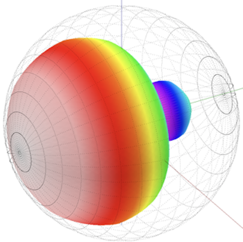
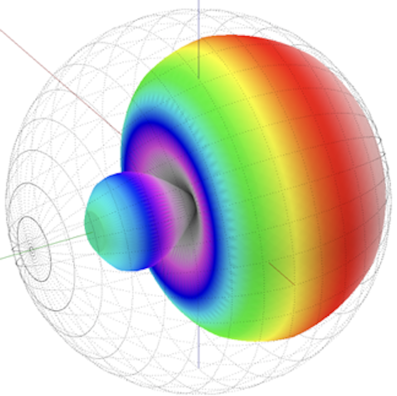
EASE 3D Audio Analysis Program of a Supercardioid pattern.
¶ Hypercardioid


EASE 3D Audio Analysis Program of a Hypercardioid pattern.
¶ Bipolar

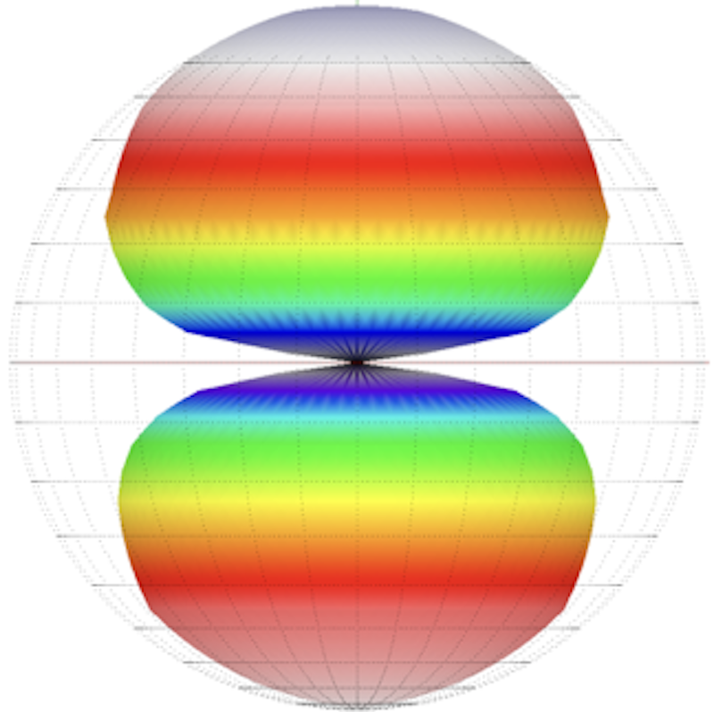
EASE 3D Audio Analysis Program of a Bipolar or "Figure 9" pattern.
¶ Polar Pattern Basics
Using a microphone that has poor off-axis coloration can deteriorate the sound of nearby sound sources. Having a source address a microphone off-axis may also result in an undesirable result. The choice of proper polar pattern in a given micing application is one of the best methods to control unwanted coloration from a nearby source.
This off-axis colouration is caused by phase cancelation that enters the microphone from both sides of the diaphragm (each side of the diaphram is essentially 180 degrees from the other). Proper microphone pattern choice and placement is the best remedy for this issue.
¶ Special Polar Patterns
Here are a few exceptions or special instances of Polar Patterns.
- Shotgun microphone — has a very narrow off-axis pickup pattern and an extended out-front pickup (long reaching)
- Parabolic reflector — utilizes a regular cardioid pattern microphone mounted inside of a half-sphere such that it focuses all incoming signal to the microphone (focused)
- Variable “D” — a special technology that stabilizes the tonal characteristics of a cardioid mic throughout an extended working distance (less proximity effect)
¶ Phantom Power
Condenser microphones utilize a capacitive circuit and require a DC voltage applied to pins 2 & 3 relative to a ground reference at pin 1. This is known as Phantom Power. Plugging in a condenser mic while that channel is open may result in a loud “pop” over the system. This pop can cause damage to different components of the system. It can also be quite unsettling to the worship team and/or audience.
¶ Microphone Handling
When using a microphone on a stand, be sure all fittings are tight before leaving. One should never drop a microphone, blow into a microphone, or set a microphone on thick carpet (static electricity). (No “mic drop!”) It is desirable for a vocalist to hold a microphone firm and steady. Unnecessary movement of the microphone can produce “Handling Noise”. This can cause unwanted rumbling or even clicking sounds to occur (jewelry making contact). A vocalist should grasp the microphone in such a way as to avoid the back of the wind screen and also, in the case of a wireless microphone, its antenna at the bottom.
¶ Vocal Microphone Technique
Proper technique as illustrated here. Directly in front of the mouth and about 1-3 finger widths from the lips:

This is a great illustration of how NOT to hold a microphone:

First, our singer is addressing the side of the microphone instead of the front of the diaphragm. As we have already learned, this would be a good example of off-axis coloration. As the singer rotates the microphone, the frequency response of the microphone changes (in a negative and inconsistent manner).
Secondly, the singer is now “cupping” (or covering) the back half of the microphone. As we have already learned, this area must be unobstructed in order for the directional characteristic of the microphone’s pattern to be fully realized. The end result of this technique can be reduced quality of the sound source as well as an increased likelihood of feedback due to the microphone’s reduced capacity for rejecting unwanted ambient sound.
¶ Proximity
Proximity effect is a change of the frequency response of a microphone, having a directional pick-up pattern, that produces an emphasis of lower frequencies. - Wikipedia.org
Proximity effect is one of the most important characteristics a microphone user needs to be aware of. Using this law to one’s advantage can greatly affect the signal before any processing occurs.
In other words, the closer a source is to the microphone, the more lower frequencies are enhanced. As a microphone is moved away from a sound source, the response tends to feel “thinner” and less “robust.” Therefore a singer, who desires to emphasize the lower frequency range of their voice, should position the microphone as close to their mouth as possible. While in times passed, singers-–many times—would move their microphone closer and farther from their mouth for volume changes, they were also varying the tonal aspect of their voice as well. With today’s tool set, we are better equipped to manage volume differences. So in most cases, as an audio engineer, we prefer a singer to hold their microphone consistently two finger-widths from their mouth at all times.


¶ Inverse Square Law
The inverse-square law, in physics, is a physical law stating that a specified physical quantity or intensity is inversely proportional to the square of the distance from the source of that physical quantity. - Wikipedia.org
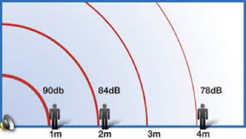
From an audio perspective, the inverse square law states that, in a free field the intensity of sound drops by 6 dB for each doubling of distance from the source.
In other words, as the microphones is moved further from the source the energy (volume) of the signal reaching the microphone decreases. This is another reason the microphone should remain as close to the mouth as possible. Understanding Proximity Effect and Inverse Square Rule, will assist you in proper utilization of microphones as well as equipping you to train your worship team members in the proper use their microphones. Again, with today’s tool set, we are better equipped to manage volume differences. So in most cases, as an audio engineer, we prefer a singer to hold their microphone two finger-widths from their mouth at all times.
As illustrated in the image below, the inverse square law also pertains to the energy (volume) of a conventional speaker source decreasing as a listener moves further from the speaker.

¶ Microphone Placement
How someone holds a microphone greatly affects the mic’s characteristics. By disturbing the rear ports of a directional microphone you are altering the designed polar pattern. Improper handling techniques adversely alter the designed pattern. In most cases this altered pattern defeats the intended result:
- Sonic quality
- Feedback suppression
- Unwanted noise rejection (audio pollution)
This is one are area as a sound engineer you can help your singer, help you. If you experience a singer holding their microphone in a manner that covers the rear of the microphone, it is to your advantage (as well as the entire audience) for you to properly educate them. This may be difficult or uncomfortable if you do not have relationship with an individual. In this case, you may point it out to the worship leader. By doing this you are both reminding the leader and better equipping them t lead well. You are also helping them obtain their desired result. Educating the folks on your stage is critical to your success as a mix engineer.
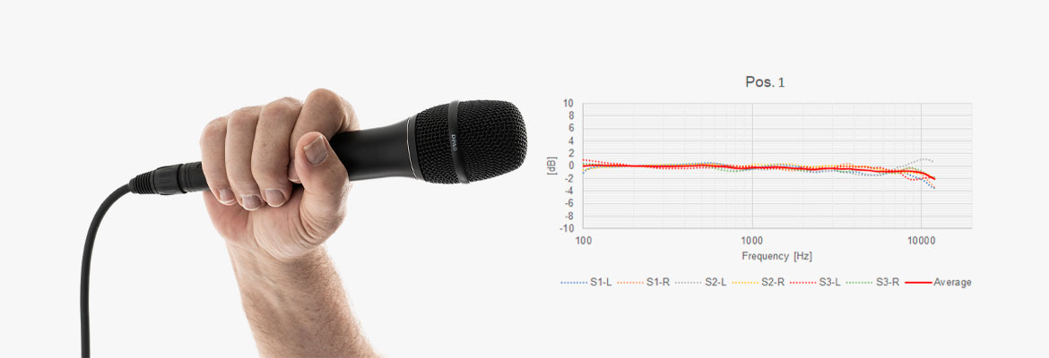
Holding the microphone at the end of the handle creates only minimal of deviations from the nominal response (ripple above approximately 3 kHz). These ripples are generally not audible.
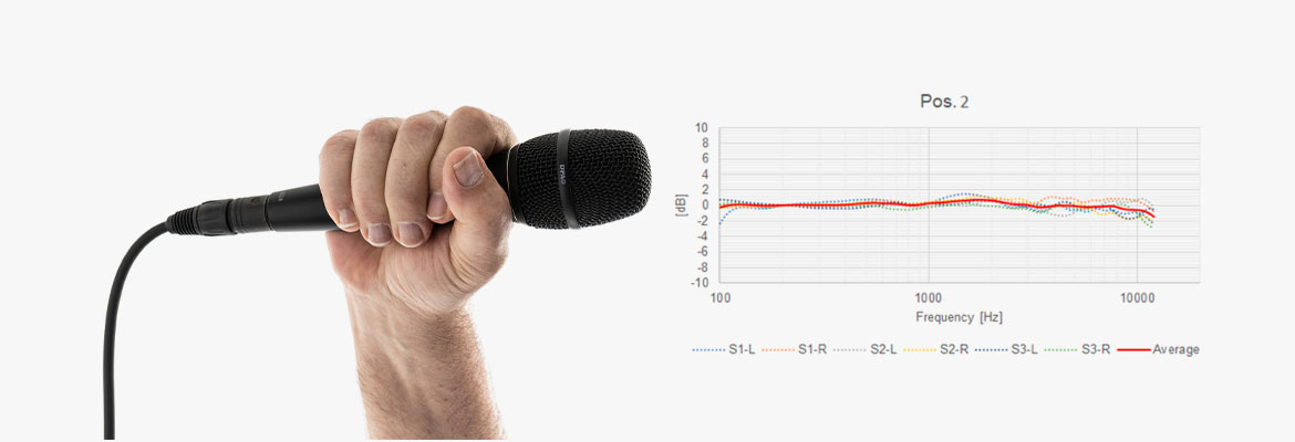
Holding the microphone at the top of the handle, just beneath the mic head, gives the ripple a somewhat higher amplitude compared to the low position. It may be audible, however still only to a minor degree.

Cupping with the index finger and the thumb flush with the front of the microphone creates resonances. The main resonance is, in one case, in the range of +9 dB @ 1.8-2.2 kHz. Another resonance is found around 10 kHz. This resonance is audible (coloring the audio) and is a source of acoustic feedback in the PA system.

This is a typical position – the hand covers half the grid and the thumb is laid over the top. The major resonance is found at around 2 kHz (low Q) and again above 6 kHz.
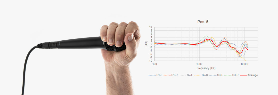
The hand surrounds the microphone head, which makes the resonances more distinct. The major resonance is found at around 2 kHz; however, at around 3-4 kHz resonances are also created due to the cavity in front of the microphone.
So, can you see why this is such a big deal?
The first rule of microphone technique is to never use two microphones when one will do the job. The 3:1 Rule is a guide to microphone placement which will minimize phase cancellations. When using two microphones to record a source, you will get the best results by placing the second microphone three times the distance from the first microphone is from the source. One common application of this rule is when area micing an ensemble or choir.

So, you may ask, ”Why so many microphones in a small area to mic a drum kit?” Well, the simplest way to look at this example is that we are actually micing each element of the drum kit individually. We are, however, inadvertently following this rule. Even though we pay close attention to phasing issues, “phasing” is a big part of stereo imaging.
¶ Variable D
As we finish up today, let’s watch this short video explanation of Variable-D technology. This video discusses the Electro-Voice line of Variable-D microphones and their unique design: