The last couple of lessons we have looked at our Audio Environment, the big pieces that make up a sound system and signal flow. Today, we will concentrate on how to make all of these pieces come together and actually get the sound from our stage (sources), through the mixer(s), into the processor and finally out of the different speakers. This will be the process we will refer to as Integration. In other words, we will be putting all of these different components together. As we integrate these components, we will need to interconnect different pieces of gear. We will refer to the result of this interconnection pathway as creating a signal chain. Just like a chain has connected links, so a sound system must have methods of connecting different pieces of equipment together. I know most of you have heard the adage, “a chain is only as strong as its weakest link?” This can also be the case with our signal chain. Through our process, we may discover a few places where these weak links may be, how to identify them and a best course of action for solving a problem.
First, we will look at the wire, connectors and cabling necessary in interconnecting all of our gear. Then, we will look at how the different pieces come together to create a working system.
¶ Cabling Basics
Let’s start out with one of the most basic and fundamental tools used in the integration of the many components in a sound system, copper wire. "Copper" can be a relative term, but is commonly accepted terminology for any wire carrying an analog signal.
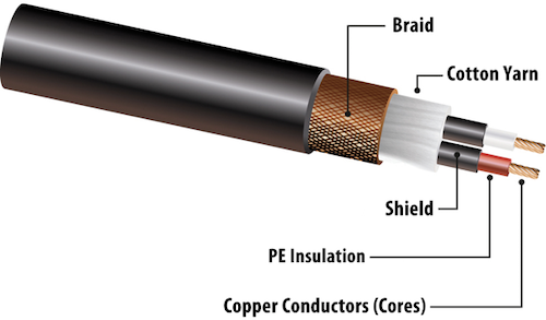
This illustration is a great example of what might be used for a balanced microphone cable. The outer jacket can be composed of anything from a very flexible rubber to an extremely durable PVC jacket. Just inside that jacket will be some type of shielding. In this illustration, this shielding is a copper braid. Other common shielding materials may include foil or even a high-tech conductive plastic shielding. Next you will see the cotton yarn, which is actually only a filler product. This usually insures a nice round cable. In this illustration the two conductors--with red and white jackets-- have an additional layer of shielding (hi-tech conductive plastic) and are comprised multi-strand copper wire.
¶ Cable Types
¶ Sheilded Single-Conductor Cable

Here we have an unbalanced (High impedance) cable. This type of cable is most commonly used as an instrument cable. One very important thing to remember about unbalanced instrument cables is that their length should be limited to 25' or less. Since the signal is unbalanced, it is more susceptible to outside interference. If your cable run needs to be longer than 25', you should use some type of interface device such as a DI (direct insertion) box or SGI system. We'll talk more about these as we dig into integrating our gear.
| Typical Construction | Example |
|---|---|
 |
Gepco GLC20 |
¶ Shielded Twisted Pair Cable
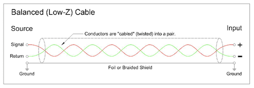
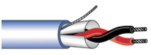
Here are representations of a balanced cable. In that we have both a positive and a negative audio signal traveling the cable, we may have much longer cable runs. This is why we tend to convert unbalanced signals into balanced signals in order to run longer distances.
| Typical Construction | Example |
|---|---|
 |
Gepco XB201M |
¶ Typical Connector Wiring
Even though this illustration shows the shield/ground wire as "floated" or not connected, for practical purposes we DO connect them these days. However, in certain circumstances, we may still "float" the ground when using a balanced cable as a "drive" line.
| Wiring Diagram | Example Cable |
|---|---|
 |
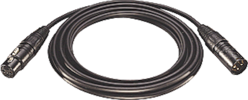 |
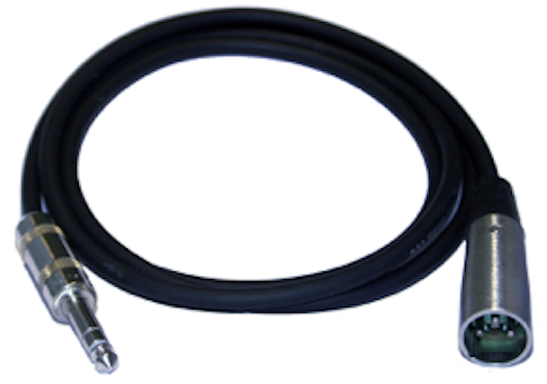
This would be a good example of a balanced drive line.
| Wiring Diagram | Example Cable |
|---|---|
 |
 |
¶ 1/4” Phone Plugs
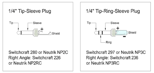
Here we have a balanced and unbalanced version of a 1/4" connector.
¶ Speaker Cables
SpeakOn connectors have become the most commonly used speaker interconnecting cable. Banana and 1/4" connectors are rarely utilized in today's modern sound systems.
Speaker cables, for professional applications, are normally a relatively large gauge wire, (18g up to 8g). In that, electricity travels on the outside of a conductor and not inside the actual conductor. Most speaker wire will be multi-stranded, which provides much more surface area for the electric current to travel.
| Connector Name | Example |
|---|---|
| Banana connector | 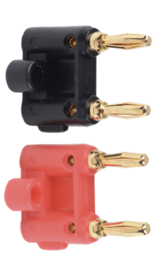 |
| SpeakOn Cable | 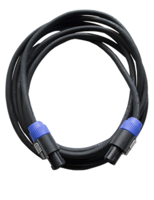 |
| 1/4" Cable | 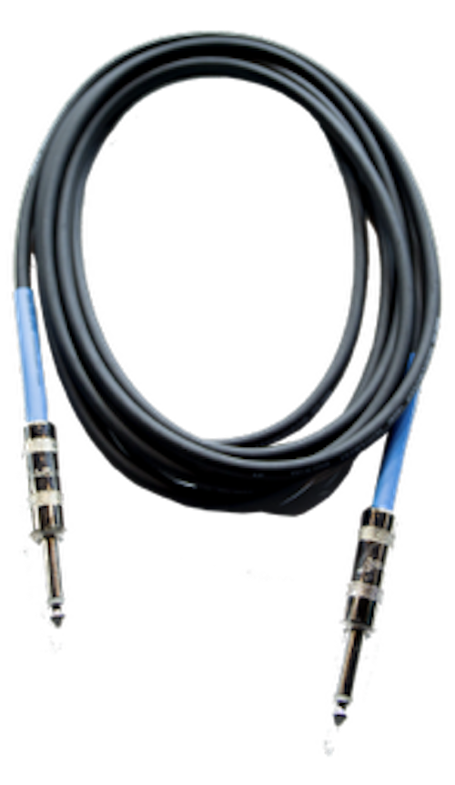 |
¶ Snakes
¶ Analogue
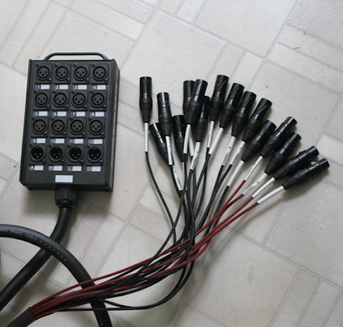
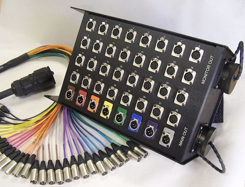
In the first picture below, you will see a simple snake cable that might be purchased at a local music store. The format of this cable is referred to as box-to-fan. The second image represents a more professional approach, this is commonly referred to as a multi-pen quick disconnect format. This format will be more commonly seen in professional touring sound systems. This format provides much more flexibility for the many different requirements of a touring sound company.
¶ Digital Snakes
With today’s digital consoles, we have the option to use a stage box with an associated digital snake. These connections utilize some type of digital format. Cables can be coaxial, Ethernet, SDI, etc. Digital Protocols include, Dante, MADI, A-Net, S/PDIF, AES/EBU, TDIF, and ADAT to name a few.
| Cable Name | Example |
|---|---|
| A-Net | 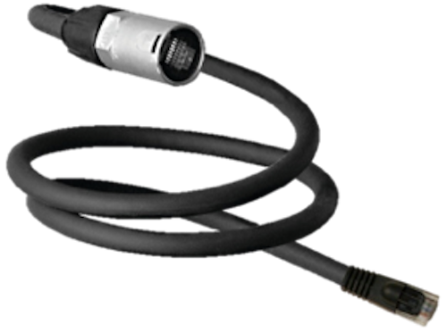 |
| Coaxial | 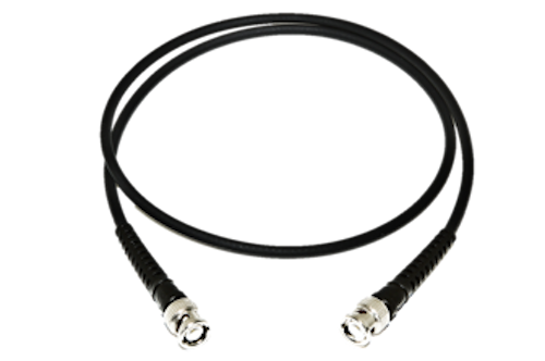 |
| S/PDIF | 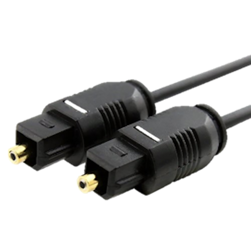 |
| Ethernet | 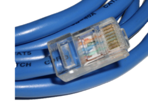 |
| RCA | 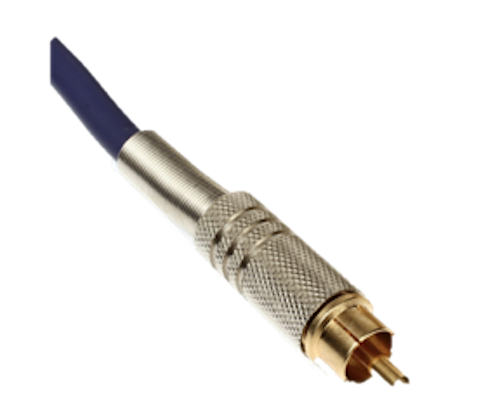 |
¶ Microphone and Instrument Cables
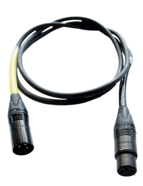
Professional balanced microphone cables utilize a balanced wiring scheme. The wire itself contains two distinct conductors along with a shield. The two conductors of this wiring will connect to pins 2 and 3 of a XLR Connector. The shield will connect to pin 1, acting as a ground/drain wire.
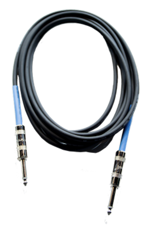
Unbalanced Instrument cables commonly consist of a coax-type wire, which has a single insulated conductor surrounded by a shield. This wire is connected to an unbalanced/TS 1/4" Connector, with the conductor connected to the tip and the shield/drain connected to the sleeve.
¶ Auxilliary Connection
These are but a few of the different wiring configurations that may be utilized for connecting different playback sources.
| Type / Name | Example |
|---|---|
| RCA to RCA | 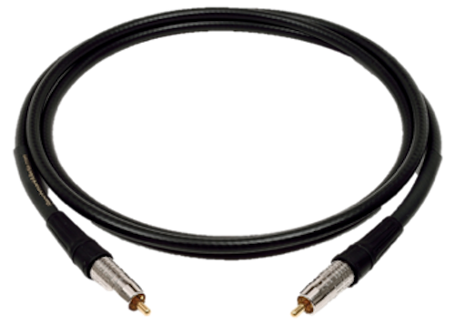 |
| XLR to 1/4" | 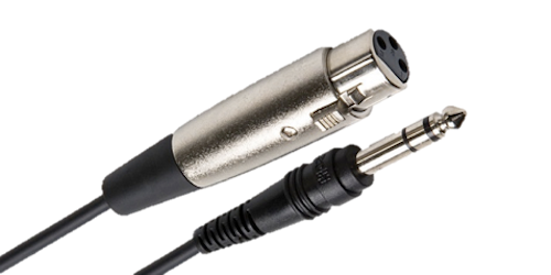 |
| 1/4" to 1/8" | 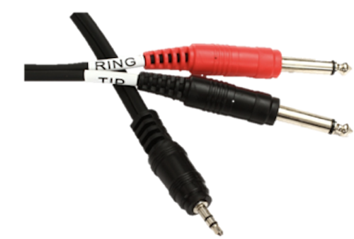 |
¶ Drive Lines
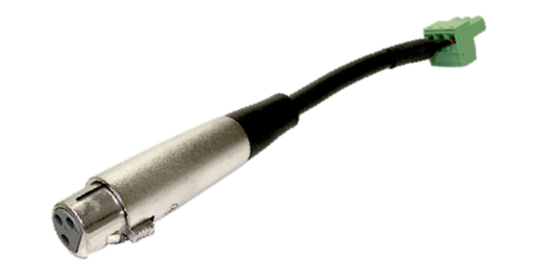
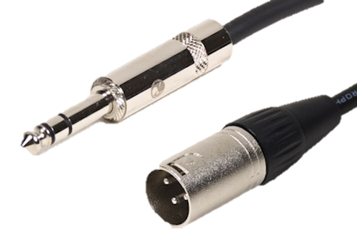
Drive lines, in a professional sound system, are most always balanced cables. Common connectors would include XLR Balanced connectors and 1/4" TRS balanced connectors. Recently, we are seeing many pieces of professional audio gear utilizing a Phoenix connectors. This is the small green connector in the illustration.
¶ Power Cables
Shown are but a few the different configurations one might see supplying power to sound equipment/instruments.
| Type / Name | Example |
|---|---|
| PowerCon | 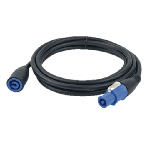 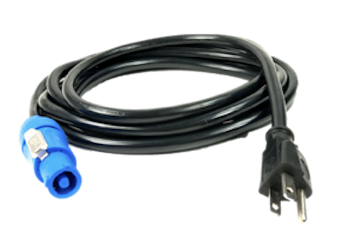 |
| IEC | 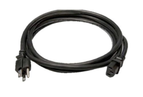 |
| Edison | 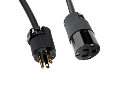 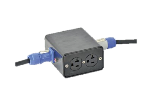 |
¶ Wireless / Radio Frequency
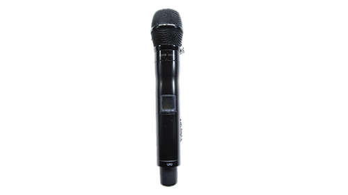 In the interest of time, we will over simplify wireless technology. For today's simple overview, lets say that our wireless systems, whether it be a wireless microphone, wireless IEM systems, or Assisted Listening Systems (ALS), utilize a radio frequency transmitter and receiver. These systems can operate in different frequency bands. These bands are regulated by the FCC for their particular usage.
One of the main purposes of wireless microphone technology can be as simple as added mobility of the user without restrictive cabling as well as the improvement of stage appearance. Even though there is no physical "copper" or digital connection between the transmitter and receiver, there IS a connection! This connection is referred to as a carrier frequency. This carrier, acts as an invisible connection that "carries" the audio between the transmitter and reciever.