In this lesson we will discuss audio power amplifiers and amplification.
Amplification is the operation of an amplifier, a natural or artificial device intended to make a signal stronger.
Now that we know what amplification is, let’s gain a better understanding of how we make a signal stronger. We do this in the audio world with the use of amplifiers.
¶ Amplifier or Amp
An amplifier is an electronic device that can increase the power of a signal (a time-varying voltage or current).
An amplifier uses electric power from a power supply to increase the amplitude of a signal. The amount of amplification provided by an amplifier is measured by its gain: the ratio of output to input. An amplifier is a circuit that can give a power gain greater than 1:1.
In this definition provided by Wikipedia, you will notice one word that we have already discussed, Gain. Remember that we defined Gain as a change in level. You will see here that in an amplifier, Gain is described as a ratio of output to input. From this definition, we can better comprehend why we can increase or decrease gain. This ratio can move in either direction from a given point.
- An amplifier can either be a standalone piece of equipment or an electrical circuit contained within another device.
- Amplification is fundamental to modern electronics, and amplifiers are widely used in almost all electronic equipment.
- An amplifier is not restricted to audio applications. Many devices require amplifier circuits.
¶ Results of an Amplifier Circuit
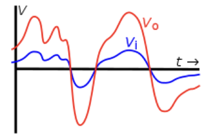
Here is a graphic representation of a circuit amplifying a signal.

Above is a graph of the input vi(t) (blue) and output voltage vo(t) (red) of an ideal linear amplifier with an arbitrary signal applied as input. Amplification means increasing the amplitude (voltage or current) of a time-varying signal by a given factor, as shown here. In this example the amplifier has a voltage gainof 3; that is at any instant vo=3vi.
¶ Amplifier Categories
Amplifiers can be categorized in different ways. One such way is by frequency of the electronic signal being amplified; audio amplifiers amplify signals in the audio (sound) range of less than 20 kHz. RF amplifiers amplify frequencies in the radio frequency range between 20 kHz and 300 GHz. Amplifier circuits can be made up of different electronic components.
¶ Amplifier Classes
The following is a series of descriptions of different classes of amplifiers. Do not try to memorize this information! It will not be on your assessment. I simply want you to know they exist.
¶ Class A
A class A amplifier has both stages of its circuit on at full power all of the time. This equates into the least efficient amplifier class. Much of the amplifier’s energy is lost through heat and not efficiently transferred to the output. However, this amplifier exhibits the most linear response with the lowest distortion of the various designs. This amplifier class is often used in radio and guitar amplifiers.
¶ Class B
A class B amplifier has only one output on at a time. The current bias switches between sinusoidal cycles. This improves the efficiency of the device at the expense of the linearity at the crossover point. This class of amplifier can be powered by a battery due to its efficiency.
¶ Class A/B
A class A/B amplifier is a hybrid design utilizing characteristics from the afore mentioned amplifiers. The A/B class allows both stages of the amplifier to be on at the same time. While one amplifier stage receives full power for ½ to 1 cycle while the other stage receives only enough to keep the stage on. This allows the second stage to respond instantly. This allows for greater efficiency than a Class A, and without the non-linear distortion of a Class B amplifier. This form of amplifier is very widely used in audio power amplifiers and self-powered speakers.
¶ Class C
A class C amplifier is only found in radio frequency transmission applications. This class turns on the one output device at a time for some percentage of a half cycle. This generates a series of pulses that represent the signal for a highly efficient but distorted design. Using radio-frequency circuits, the distortion can be managed and the high efficiency utilized for high output transmission of radio signals.
¶ Class D
Class D amplifiers, also known as a switching amplifier, use transistors as electronic switches that can be either on or off. The amplifier implements a technique such as pulse-width modulation, delta-sigma modulation or pulse-density modulation to convert the input signal into a stream of pulses wherein the time average power of the pulses is proportional to the original analogue signal. The frequency of the pulses is many times higher than the highest frequency of the input signal so that a passive low-pass filter can be used to smooth the pulses and convert them back to an analogue signal. Class D amplifiers are very efficient in comparison to Class AB, which allows for a smaller and lighter form factors, as well as much cooler operation. They excel at a band limited high power applications, such as for driving subwoofers.
¶ Amplifier Specification Terms
Let’s take a look just at a few specifications associated with an audio amplifier.
First, let’s talk about power ratings. This rating may not be what the average person might expect. There are different ratings that can be based on certain conditions and applications. There are also different equations that determine these rating. Here are some (over simplified) descriptions.
- Peak — is considered the peak output of the amplifier for short intervals.
- Average or RMS — is roughly .707 of the peak power rating over time, where inversely, 1.414 is the peak value of an RMS signal. (for you math geeks)
- Continuous/Long term — Is the output capability of a power amplifier to continuously produce a constant signal over a long period of time.
Slew rate is the measure of ability of an amplifier to respond to very fast changes in signal voltage.
- The slope of the ramping output voltage is called the slew rate of the amplifier.
- An amplifier’s slew rate can affect its ability to render musical transients and complex waveforms with accuracy at high power levels .
- The higher the slew rate, the better, up to a point. Too high a slew rate in a power amplifier may be associated with too wide a bandwidth, which can allow the amplifier to pass radio frequency (RF) signals that serve only to increase distortion, waste power, and overheat drivers.
Slew rate speaks to the speed of the amplifier and its ability to accurately reproduce very fast “high transient” signals.
Damping factor value, in loudspeaker systems, between a particular loudspeaker and a particular amplifier describes the ability of the amplifier to control undesirable movement of the speaker cone near the resonant frequency of the speaker system. It is usually used in the context of low-frequency driver behaviour, and especially so in the case of electrodynamic drivers, which use a magnetic motor to generate the forces which move the diaphragm.
A high damping factor indicates that an amplifier will have greater control over the movement of the speaker cone, particularly in the bass region.
¶ Amplifier Operation Modes
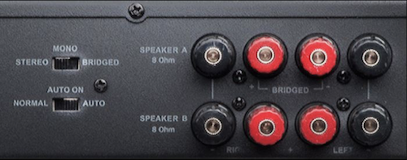
When connecting the outputs of an amplifier, you may encounter these terms:
- Stereo Mode: Two separate inputs routed to two separate outputs
- Mono Mode: One input routed to two separate outputs
- Bridged Mono Mode: One input routed to a special output port (or wiring configuration) which combines both output channels into a single output
These modes or options, speak to the different modes which the amplifier can operate in. The proper selection of modes and corresponding output wiring configurations can determine how safely and efficiently your amplifier can operate with the speaker(s) it is paired with. We will not get into all of the math and details behind these options today. The reason for their introduction is simply for you to realize they exist and that they are important. At this point, I would recommend that you have an experienced professional assist you with the proper set-up of your amplifier/speaker system.
Let’s look briefly at how these modes affect a power amplifier’s output ratings.

When connecting the outputs of an amplifier, you may encounter these terms.
These modes or options, speak to the different modes which the amplifier can operate in. The proper selection of modes and corresponding output wiring configurations can determine how safely and efficiently your amplifier can operate with the speaker(s) it is paired with.
We will not get into all of the math and details behind these options today. The reason for their introduction is simply for you to realize they exist and that they are important. At this point, I would recommend that you have an experienced professional assist you with the proper set-up of your amplifier/speaker system.
The next portion will give us a look at the different amplifier ratings associated with each of these operation modes.
Example - Power output level, continuous average sine wave power at less than 0.05% THD, 20 Hz to 20 kHz:
- Stereo (8 Ohms) — 240 watts/channel
Two separate inputs routed to two separate outputs - Stereo (4 Ohms) — 400 watts/channel
One input routed to two separate outputs - Bridged Mono (8 Ohms) — 800 watts/channel
One input routed to a special output port which combines both output channels into a single output
(Electrical impedance is the measure of the opposition that a circuit presents to a current when a voltage is applied. )
You will notice that NOW we have added yet another variable, Ohms or impedance. Impedance is the resistance of the circuit (namely the speaker components) when the voltage of the amplifier circuit is applied. Now you can see why I stated earlier that an amplifier’s ratings are not always as simple what one might expect. Therefore properly matching an amplifier to desired speaker(s) is very important. This is one of the reasons more and more speaker manufacturers are integrating specially designed amplifiers into the speaker cabinet. The difference between impedance and resistance is that impedance is measured under a load.
¶ Matching Amplifier to Speakers
An Amplifier with inadequate power capability can, in fact, damage loudspeakers by stressing them more than a larger amplifier (the smaller amp may be driven into clipping, which produces a dense harmonic structure and artificially steep waveforms (resembling a square wave); this can overheat high frequency driver voice coils by feeding them more power than the program would otherwise have provided.)
The amplifier must also be able handle the load that the loudspeakers present. In order to avoid excessively loading the amplifier when multiple loudspeakers are connected to a single output, we need to know the impedance of each individual loudspeaker and we must calculate the net load impedance.
This is why we recommend that you utilize a professional integrator to either provide, connect or at least design a speaker/amplifier system for your needs.
It is recommended that an audio amplifier is chosen that can produce more power than that of the speaker’s rating:
- Allows the amplifier to work less
- Provides headroom allowing the amplifier to reproduce transients better
- Can actually help protect the speaker, in that there is less chance that the amplifier is driven into clipping
This is an overly simplified rule-of-thumb, but it can keep you out of trouble.