In a sound reinforcement system, loudspeakers play an important role as the final link between the sound source and the audience. Surprisingly, they are also the least understood components of that equipment chain.
Loudspeaker is a generic term used to describe a wide variety of transducers that convert electrical energy into acoustical energy, or sound. The term also is commonly used to refer to systems of two or more transducers in a single enclosure, with or without a crossover.
For the sake of clarity, we will use the term driver to refer to individual transducers, and loudspeaker to refer to system.
¶ Acoustic Transduction
Loudspeakers convert electrical energy into acoustical energy. The vast majority of loudspeakers—both high and low frequency—are built around electromagnetic linear motors.

Here you see the main components of an electromagnetic motor (transducer):
- Bottom plate
- Magnet
- Coil assembly – (former with wire coil)
- Gap
- Pole piece
- Diaphragm
A coil of wire is surrounded by a permanent magnet. The permanent magnet sets up stationary lines of magnetic force. If a direct current is now passed through the coil, the flow of electrons in the wire creates a second magnetic field around the coil. The polarity (north-south) of this field is dependent on the direction of current flow through the wire. The electromagnetic field interacts with that of the permanent magnet. Assuming that the permanent magnet’s position is fixed, the force resulting from the interaction of the two fields causes the coil to move. If the flow of the current in the coil is now reversed, then the polarity of the electromagnetic field is also reversed. This reverses the direction of the force acting on the coil, causing it to move in the opposite direction. If the direction of the current is repeatedly reversed, the coil will move back and forth within the field of the magnet. The motion of the coil will be a physical representation of the alternations of the current. This is the general principle by which electromagnetic motors work.
The coil is suspended in the gap, concentric with the pole piece. Alternating current from the power amplifier passes through the coil, causing it to move back and forth in the gap. The coil is attached to a suitable diaphragm, which couples its mechanical motion to the air.
So, what makes the sound? The mechanics of the coil attached to the diaphragm moving within the magnetic field moves the air around it, therefore producing sound waves. The movement of the diaphragm produces sound waves. So, the electric power from the amplifier is converted to mechanical energy through the movement of the diaphragm.
¶ Low Frequency Drivers
Efficient reproduction of low frequencies requires that a large volume of air can be moved. This, in turn, requires one or both of the following: Long diaphragm excursion and/or large diaphragm area. In sound reinforcement, low frequency drivers are invariably electromagnetic linear motors with cone diaphragms. When flush mounted on the front of an enclosure (i.e., without a horn), this type of driver is also known as a direct radiator.
¶ Low Frequency Cone Driver
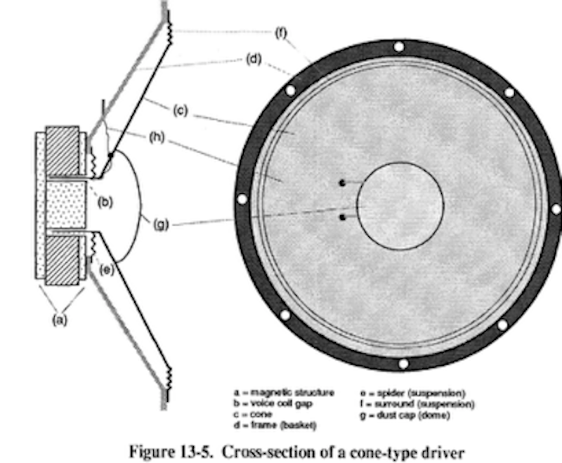
In a cross section of a typical cone low frequency driver you can see the coil is coupled to a cone shaped diaphragm. The driver’s diaphragm/coil assembly is attached to the frame—also known as a basket—at two points. The spider accomplishes two tasks, it anchors the apex of the cone, and it centres the coil in the gap. The surround anchors the base of the cone to the frame. Together, these elements are referred to as the suspension.
Cone drivers can be different sizes. The driver size is specified in terms of cone diameter, measured at the base of the cone. Standard sizes for low frequency drivers in a sound reinforcement are 12, 15, and 18 inches.
¶ High Frequency Drivers
High frequency horn design is a fairly refined art. The most important attribute that we desire in a high frequency horn for sound reinforcement is a controlled dispersion pattern. The horn should distribute high frequencies over a defined angle both in the horizontal and vertical axes. To the extent that is possible acoustically, the angle of dispersion should be consistent over the full frequency range of interest—usually up to about 16kHz. That way the sound quality off axis will be close to that on axis.
However, we do not live in a perfect world, therefore, you will commonly see specification or graphs showing varying coverage at different frequencies.
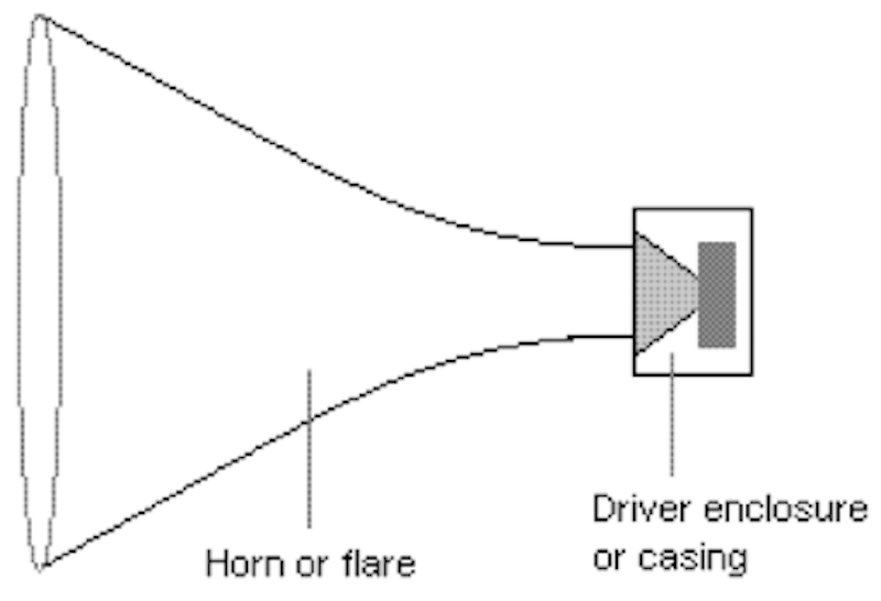
From this drawing, you will notice the horn or flare. This is the portion of the high frequency “horn” that controls the dispersion angle. Depending on the horn’s design, different results are possible.
¶ Exponential Horns
Exponential horns employ exponential flare rates, often with different rates for the horizontal and vertical expansions, and sometimes with compound rates.
¶ Radial Horns
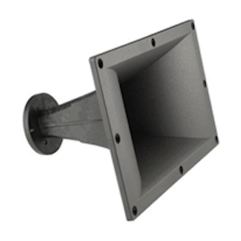
Radial horns are formed by defining a flare in two dimensions, then rotating that shape through a given arc around a central origin.

¶ Constant Directivity or CD Horns
Constant directivity or CD horns employ compound flare rates, with different rate in the horizontal and vertical axes. CD horns provide the most controlled dispersion pattern.

¶ Crossovers
It is necessary to divide the full-range audio signal into its low and high frequency components, directing each only to the appropriate driver(s). This function is called crossover. Two generic types of crossover are in common use in sound reinforcement: High-level passive networks, and low level active networks.
- Passive high-level crossovers are simple networks that are inserted between the power amplifier output and the drivers, often enclosed within the loudspeaker cabinet.
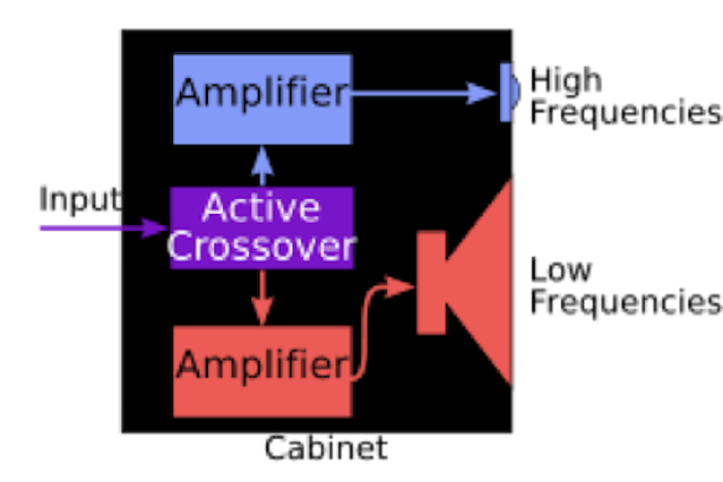
- Active crossover networks are designed to be inserted in the signal chain before the power amplifier. They thus work at far lower signal levels than do passive, high-level crossovers. Since active crossovers divide up the total frequency range before the power amplifier, separate amplifier channels are required for each driver or set of drivers. Another term for this type of unit is an electronic crossover.
In spite of the fact that they can increase the total cost of a smaller system, active crossovers are widely used in professional sound because they offer significant advantages in systems performance, as detailed in the following text. They can actually save money in large installations.
- Headroom — active, low level crossovers allow different frequency material to be routed to its own power amplifier, avoiding clipping and allowing for more headroom.
- Damping — an amplifier with a high dampening factor can exert greater control over the motions of a loudspeaker diaphragm than an amplifier with a low damping factor, so high damping may improve sound quality.
- Distortion — An active, low level crossover avoids any possible non-linearity’s that might be caused by a passive, high level crossover.
In our modern era, tis process is many times accomplished within a Digital Signal Processing unit or DSP.
¶ Full-Range Speakers
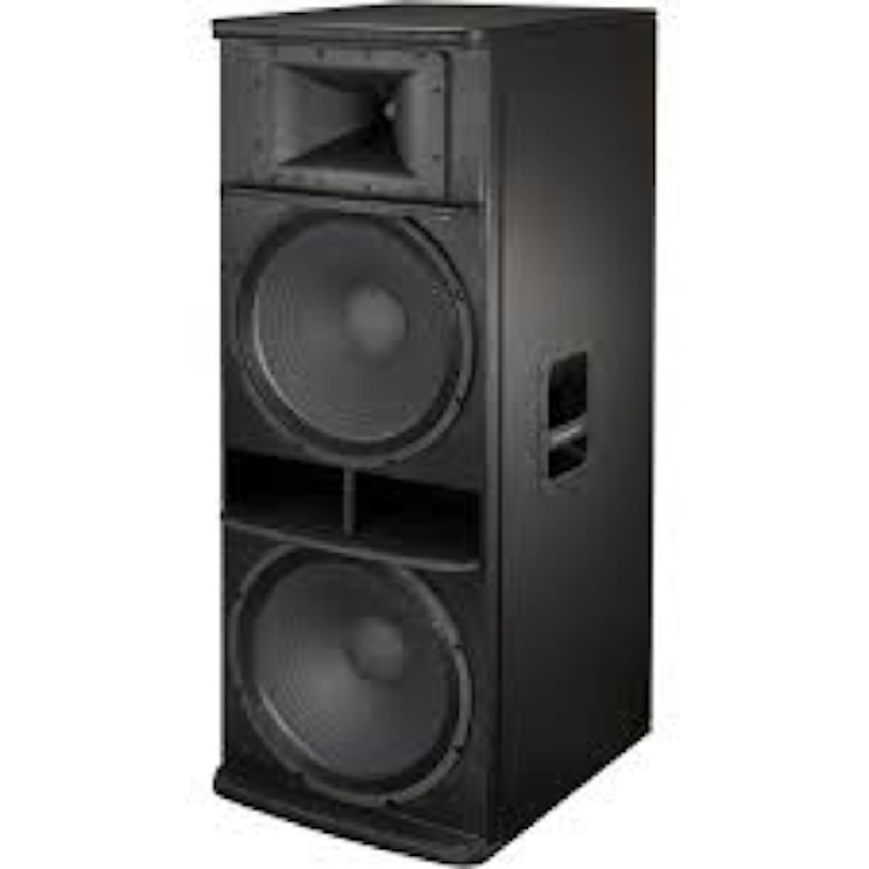
By using an appropriate crossover to combine two or more drivers that reproduce different frequency ands, loudspeaker systems can be created that cover most of the audio frequency range. Such systems are referred to as full range loudspeakers. Even though this is a true statement, many so called “full range” speakers are used with additional sub-woofer cabinets to extend the lower frequency range to provide a more desirable musical experience. Sub-woofer speakers are not required for a speech only systems in that the lower frequency is not required for reproduction of the speech range.
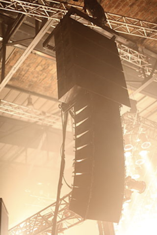
¶ Line-Array Speaker System
A loudspeaker system that is made up of a number of usually identical loudspeaker elements mounted in a line and fed in phase, to create a near-line source of sound. The distance between adjacent drivers is close enough that they constructively interfere with each other to send sound waves farther than traditional horn-loaded loudspeakers, and with a more evenly distributed sound output pattern.
¶ Self-Powered Speakers
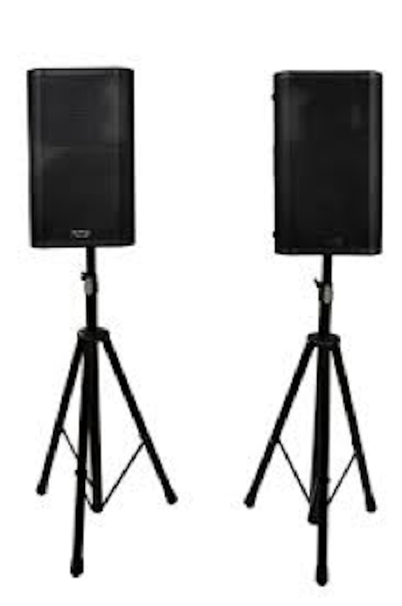
Many speaker systems now have highly customized amplifiers built within their enclosures. Some of these speaker systems also employ internal crossovers and some even possess DSP units. These speakers may be a small full range speaker designed to be placed on a portable speaker stand. Large format line-array speaker systems also utilize integrated amplifiers and DSP. From the smallest full range “speaker-on-a-stick” to the largest concert line-array system, many of the manufacturers have spent much time and resources to design and develop systems that have amazing quality and durability.
Here is an example of a simple “speaker on a stick” design:
¶ Identifying Speaker System Problems
¶ Overexertion
When the power amplifier—or another signal processing element in the chain—is asked to deliver an output signal level that exceeds its capabilities, clipping occurs. Over excursion is the driver’s equivalent of amplifier clipping
¶ Intermodulation Distortion
Under some conditions, interaction can occur in the loudspeaker between two or more frequencies in a program, producing extra frequencies that were not present in the original signal. This is called intermodulation, and the extra frequencies that are produced are a form of distortion.
¶ Speaker Component Damage
¶ Separated Cone Driver
Damage may occur to a low or mid frequency “cone” driver from many different things. Damage may be detected in the form of a buzz or rattle from a component when its cone has separated from either the surround or dust cover. This would be considered distortion, in that the speaker is not simply reproducing the intended material. This problem may be spotted by simple visual inspection or it may be detected with the use of a frequency sweeping tone generator.
¶ Fried/Charred High Frequency Voice Coil
The wire wrappings of a high frequency driver may be charred or even melted due to heat produced by over-driving the component. This is caused by the component being over-heated. In this state the driver’s output may be distorted or possibly non-existent due to the damage. This problem may be spotted by simple visual inspection or it may be detected with the use of a multi-meter (usually show as an open circuit or a short circuit). Some high powered high frequency drivers utilize a feri-fluid liquid to help keep the driver from overheating.
¶ Mechanical Distortion
This form of distortion is not produced electronically, instead it can be generated mechanically due to something within the speaker vibrating. This can actually be one of the more difficult types of distortion to pinpoint. You may locate the problem with the use of a frequency sweeping tone generator to excite to the frequency that is producing the unwanted vibration.